- 您现在的位置:买卖IC网 > Sheet目录2008 > MAX1159AEUI+ (Maxim Integrated Products)IC ADC 14BIT 135KSPS 28-TSSOP
powers down the reference and reference buffer after
completing a conversion. The reference and reference
buffer require a minimum of 12ms (CREFADJ = 0.1F,
CREF = 10F) to power up and settle from shutdown.
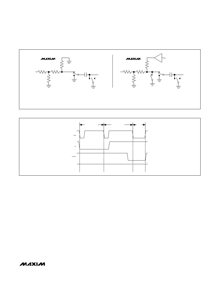
The state of R/C during the second falling edge of CS
selects which power-down mode the MAX1157/
MAX1159/MAX1175 enters upon conversion comple-
tion. Holding R/C low causes the MAX1157/MAX1159/
MAX1175 to enter standby mode. The reference and
buffer are left on after the conversion completes. R/C
high causes the MAX1157/MAX1159/MAX1175 to enter
shutdown mode and power down the reference and
buffer after conversion (see Figures 5 and 6). Set the
voltage at REF high during the second falling edge of
CS to realize the lowest current operation.
Standby Mode
While in standby mode, the supply current is less than
3.7mA (typ). The next falling edge of CS with R/C low
causes the MAX1157/MAX1159/MAX1175 to exit stand-
by mode and begin acquisition. The reference and ref-
erence buffer remain active to allow quick turn-on time.
MAX1157/MAX1159/MAX1175
14-Bit, 135ksps, Single-Supply ADCs with
Bipolar Analog Input Range
_______________________________________________________________________________________
9
Figure 4. Equivalent Input Circuit
MAX1157
R2
R3
161
3.4k
TRACK
HOLD
S1, S2 = T/H SWITCH
S3 = POWER-DOWN
(MAX1159/MAX1175
ONLY)
S1
CHOLD
30pF
S2
AIN
MAX1159/MAX1175
R2
R3
161
3.4k
S3
POWER-
DOWN
TRACK
HOLD
REF
R2 = 7.85k
(MAX1159)
OR 3.92k
(MAX1157/MAX1175)
R3 = 5.45k
(MAX1159)
OR 17.79k
(MAX1157/MAX1175)
S1
CHOLD
30pF
S2
AIN
T/H OUT
Figure 5. Selecting Standby Mode
CS
R/C
EOC
REF AND
BUFFER
POWER
ACQUISITION
CONVERSION
DATA
OUT
发布紧急采购,3分钟左右您将得到回复。
相关PDF资料
MAX11602EEE+
IC ADC SERIAL 8BIT 8CH 16-QSOP
MAX11610EEE+T
IC ADC SERIAL 10BIT 12CH 16-QSOP
MAX11616EEE+T
IC ADC SERIAL 12BIT 12CH 16-QSOP
MAX1162AEUB+T
IC ADC 16BIT 200KSPS 10-MSOP
MAX11637EEE+T
IC ADC 12BIT 8CH 16QSOP
MAX11643EEG+T
IC ADC 8BIT 8CH 24QSOP
MAX11645EUA+T
IC ADC 12BIT I2C/SRL 1CH 8UMAX
MAX11647EUA+T
IC ADC 10BIT I2C 94.4KSPS 8UMAX
相关代理商/技术参数
MAX1159AEUI+T
功能描述:模数转换器 - ADC 14-Bit 135ksps 4.2V Precision ADC RoHS:否 制造商:Texas Instruments 通道数量:2 结构:Sigma-Delta 转换速率:125 SPs to 8 KSPs 分辨率:24 bit 输入类型:Differential 信噪比:107 dB 接口类型:SPI 工作电源电压:1.7 V to 3.6 V, 2.7 V to 5.25 V 最大工作温度:+ 85 C 安装风格:SMD/SMT 封装 / 箱体:VQFN-32
MAX1159AEUI-T
功能描述:模数转换器 - ADC RoHS:否 制造商:Texas Instruments 通道数量:2 结构:Sigma-Delta 转换速率:125 SPs to 8 KSPs 分辨率:24 bit 输入类型:Differential 信噪比:107 dB 接口类型:SPI 工作电源电压:1.7 V to 3.6 V, 2.7 V to 5.25 V 最大工作温度:+ 85 C 安装风格:SMD/SMT 封装 / 箱体:VQFN-32
MAX1159BCUI
功能描述:模数转换器 - ADC RoHS:否 制造商:Texas Instruments 通道数量:2 结构:Sigma-Delta 转换速率:125 SPs to 8 KSPs 分辨率:24 bit 输入类型:Differential 信噪比:107 dB 接口类型:SPI 工作电源电压:1.7 V to 3.6 V, 2.7 V to 5.25 V 最大工作温度:+ 85 C 安装风格:SMD/SMT 封装 / 箱体:VQFN-32
MAX1159BCUI+
功能描述:模数转换器 - ADC 14-Bit 135ksps 4.2V Precision ADC RoHS:否 制造商:Texas Instruments 通道数量:2 结构:Sigma-Delta 转换速率:125 SPs to 8 KSPs 分辨率:24 bit 输入类型:Differential 信噪比:107 dB 接口类型:SPI 工作电源电压:1.7 V to 3.6 V, 2.7 V to 5.25 V 最大工作温度:+ 85 C 安装风格:SMD/SMT 封装 / 箱体:VQFN-32
MAX1159BCUI+T
功能描述:模数转换器 - ADC 14-Bit 135ksps 4.2V Precision ADC RoHS:否 制造商:Texas Instruments 通道数量:2 结构:Sigma-Delta 转换速率:125 SPs to 8 KSPs 分辨率:24 bit 输入类型:Differential 信噪比:107 dB 接口类型:SPI 工作电源电压:1.7 V to 3.6 V, 2.7 V to 5.25 V 最大工作温度:+ 85 C 安装风格:SMD/SMT 封装 / 箱体:VQFN-32
MAX1159BCUI-T
功能描述:模数转换器 - ADC RoHS:否 制造商:Texas Instruments 通道数量:2 结构:Sigma-Delta 转换速率:125 SPs to 8 KSPs 分辨率:24 bit 输入类型:Differential 信噪比:107 dB 接口类型:SPI 工作电源电压:1.7 V to 3.6 V, 2.7 V to 5.25 V 最大工作温度:+ 85 C 安装风格:SMD/SMT 封装 / 箱体:VQFN-32
MAX1159BEUI
功能描述:模数转换器 - ADC RoHS:否 制造商:Texas Instruments 通道数量:2 结构:Sigma-Delta 转换速率:125 SPs to 8 KSPs 分辨率:24 bit 输入类型:Differential 信噪比:107 dB 接口类型:SPI 工作电源电压:1.7 V to 3.6 V, 2.7 V to 5.25 V 最大工作温度:+ 85 C 安装风格:SMD/SMT 封装 / 箱体:VQFN-32
MAX1159BEUI+
功能描述:模数转换器 - ADC 14-Bit 135ksps 4.2V Precision ADC RoHS:否 制造商:Texas Instruments 通道数量:2 结构:Sigma-Delta 转换速率:125 SPs to 8 KSPs 分辨率:24 bit 输入类型:Differential 信噪比:107 dB 接口类型:SPI 工作电源电压:1.7 V to 3.6 V, 2.7 V to 5.25 V 最大工作温度:+ 85 C 安装风格:SMD/SMT 封装 / 箱体:VQFN-32